The goal of this lab was to practice correcting atmospheric interference of remotely sensed images. Using ERDAS Imagine, ArcMap, and Microsoft Excel, a series of multispectral images and the various spectral bands they are comprised of were corrected to represent true surface reflectance of land features.
Methods
Part 1: Absolute atmospheric correction using Empirical Line Calibration (ELC)
In the first part of this lab, a multispectral image of the greater Eau Claire area taken in 2011 by the Landsat 5 Thematic Mapper (TM) satellite, was corrected to represent at-surface spectral profiles of land features. By referencing libraries of typical spectral profiles of various surfaces, the Spectral Analysis Workstation tool was used to convert brightness values of surface features collected by the sensor, to a more typical set of brightness values for those surface features at ground level.
 |
| Figure 1: Select Atmospheric Adjustment tool in Spectral Analysis Workstation window. |
 |
| Figure 2: Adjusting spectral profiles of surface features with the Atmospheric Adjustment tool in the Spectral Analysis Workstation model in ERDAS Imagine. |
After a sample point was collected for each surface feature, the tool was ran and generated an output image that was used to compare the spectral profiles of surface features after atmospheric correction with those of the original image (see Results).
Part II: Absolute atmospheric correction using enhanced image-based Dark Object Subtraction (DOS)
In the second part of this lab, a multispectral image of the greater Eau Claire area taken in 2011 by the same sensor as the image used in Part 1 (Landsat 5 TM) was corrected for atmospheric interference using the DOS method. This method converts the brightness values (spectral reflectance) of the original image to at-sensor spectral reflectance values, then to true surface reflectance values by using sensor gain and offset, solar irradiance and zenith angle, atmospheric scattering and absorption, and path radiance in two subsequent equations (Figures 3 and 4).
 |
| Figure 3: At-sensor spectral radiance equation. |
 |
| Figure 4: True surface reflectance equation. |
 |
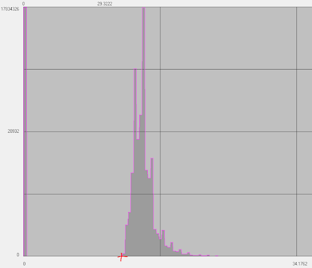
| Figure 5: Visualization of path radiance value for band 1 (located in layer histogram). |
 |
| Figure 6: Model that generates at-sensor radiance and true surface reflectance images of all 6 bands. |
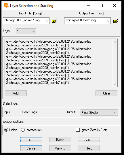
Once all of the true surface reflectance images were created, a Layer Stack operation was performed to generate a multispectral image containing true surface reflectance brightness values.
 |
| Figure 7: Running a Layer Stack model on the true surface reflectance individual band images. |
In the third and final part of this lab, two images capturing the same greater Chicago area from two different time signatures were combined using the Spectral Profile Viewer to collect the spectral profiles of various surface features in the images. Then, the mean brightness values of each spectral band in both images were brought into Microsoft Excel to generate a linear regression model. The values of which were then used to normalize the spectral signatures of the surface features between the two image dates.
First, the 2000 and 2009 images were brought into separate viewers in ERDAS Imagine. Then, the Spectral Profile Viewer was used to collect six samples in Lake Michigan, five samples of urban and built-up areas, and four samples of on-land water bodies (Figures 8 and 9).
 |
| Figure 8: Various surface feature sample point locations. |
 |
| Figure 9: Spectral Profiles of sample points. |
 |
| Figure 10: Tabular data and Linear Regression Model of mean pixel values for both images. |
 |
| Figure 11: Equation used for normalizing at-sensor radiance of the image bands. |
 |
| Figure 12: Model for normalizing the individual image bands of the 2009 Chicago multispectral image. |
 |
| Figure 13: Layer stacking the individually corrected at-sensor spectral radiance band images. |
 |
| Figure 14: Comparing spectral profile of aluminum roof for original image (left) and corrected image (right). |
 |
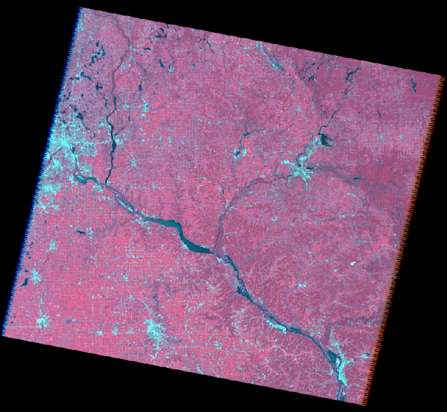
| Figure 15: Multispectral composite for DOS method. |
 |
| Figure 16: Multispectral composite for Multidate Image Normalization method. |
Conclusion
For part one, the empirical line calibration method turned out to be a decent method for adjusting for atmospheric interference. Although using the general spectral libraries doesn't provide the most accurate spectral correction, it does reduce the atmospheric windows that are a result of atmospheric interference and, in that regard, are helpful in getting a glimpse of surface reflectance.
For part two, the dark object subtraction method turned out to be the most accurate form of adjusting for atmospheric interference. By using constants from the satellite itself, values from the image data, and other mathematical constants (ie. pi), the calculations performed on each spectral band to eliminate the interference of the atmosphere generated particularly accurate image bands that were then stacked to produce an accurate multispectral image also.
For part three, the multidate image normalization method would've been a great method for eliminating variance in atmospheric conditions between two dates if the procedure was performed properly. Having misunderstood the instructions, the linear regression model used to calibrate the image bands was incorrect. Only 7 mean brightness values were used for each image and only one linear regression model was produced when, in actuality, 10 mean brightness values should've been used for each image band to generate 6 linear regression models. The lack of effectiveness in this effort was shown when studying the spectral profiles of the original and "corrected" images. It was even visible in the resulting image, as it appears very bright and has low spatial resolution.
Overall, it was very interesting to see the difference atmospheric correction had on the spectral profiles of surface features and helped reiterate the importance of atmospheric correction. The methods used in this lab have their differences in quality, but also have their particular uses and functions. For instance, if an image analyst only needs a rough idea of surface feature profiles and/or quick classification, the empirical line calibration method could suffice instead of the time-intensive, but more accurate method of dark object subtraction.
Sources
Data provided by Dr. Cyril Wilson and Landsat 5 TM
Image processing and atmospheric correction performed in ERDAS Imagine and ArcMap


No comments:
Post a Comment